Posts

Dispatching

The compute pipeline is compiled, a descriptor set created and a buffer filled with initial values. So the remaining step is to invoke the compute shader for each particle every frame to receive discrete changes and render them. But instead of recording draw calls you record a dispatch with a selected amount of invocations. A support function will be able to calculate the required amount of work group invocations to launch a thread for each particle depending on the work groups size. Similar as with draw calls the used descriptor sets have to be provided with their binding indices. auto cmdStream = core.createCommandStream(vkcv::QueueType::Graphics); /* Requesting a graphics queue for the command stream here is fine because * most devices expose at least one queue to support graphics and compute tasks * * Using such a queue allows dropping any synchronization between multiple queues * by recording compute dispatching and draw calls in just one command buffer. */ vkcv::Pus...

Compute pipeline

Compute shader For your compute pipeline you need only one shader in comparison to a graphics pipeline. This does mean that you have to specify more things for it to optimize certain aspects. For example compute shaders are dispatched in so called work groups which then distribute their invocations on threads from your GPU. To optimize throughput and synchronization the pipeline still expects you to define the size of your work groups in a compute shader. The application will only dispatch an amount of work groups afterwards but more about this topic later on in the part about dispatching . shaders/shader.comp #version 450 core // work group size (x = 256, y = 1, z = 1) layout(local_size_x = 256) in; // particle structure struct Particle { vec3 position; float mass; vec3 velocity; float lifetime; }; // particles via shared storage buffer layout(std430, set = 0, binding = 0) buffer particleBuffer { Particle particles[]; }; // relative time difference via push const...

Buffer creation

Structure First of all to simulate a lot of particles, you need data for a lot of particles. In this example here, it means you need positions, velocities, masses and lifetime. So you can start by defining a structure in C++ for a particle like this: #include<glm/glm.hpp> struct Particle { glm::vec3 position; float mass; glm::vec3 velocity; float lifetime; }; Notice that vec3 attributes and float attributes are used alternately. This is actually intentional! Different types of your attributes in structures will be aligned differently on GPU and CPU. So depending on the order of your attributes a structure may cost more memory in a buffer for each entry which results in wasting bandwidth and even worse: When you don't make sure alignment on CPU and GPU match for each attribute, your application might not work properly at all. In the code example above you get the same alignment on CPU and GPU because the mass and lifetime fill the gap between two vec3 ...

How to simulate particles

Image
Since Vulkan was not only designed for rendering but for compute tasks as well, the following guide will focus on this. For this task the guide will show you how to simulate and render particles because this is something a GPU can do extremely well. Each particle can potentially be simulated in parallel via a compute shader . The rendering of each particle will not be included in detail with all shaders but the guide should give you a good idea how to do it yourself. So these are the individual steps of this guide: Step 1 - Buffer creation Step 2 - Compute pipeline Step 3 - Dispatching You can also find the whole list of steps in the overview page of this blog and this here is a first visual hint what the goal of this guide could be:  Previous Next

Scene rendering

Image
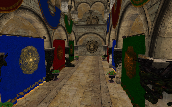
Now with the shaders compiled, vertex layout configured and descriptor set layouts specified, the rendering can begin. In a similar way as with the single triangle, you need to record draw calls. But this time a draw call per mesh will be recorded. Each draw call will automatically use the descriptor set of the individual material from the given mesh. But push constants as well as additional descriptor sets need to be configured in a callback if used (in the example here only the push constants get filled with individual data): auto recordMesh = [](const glm::mat4& mvp, // mvp matrix of mesh const glm::mat4& model, // model matrix of mesh vkcv::PushConstants& pushConstants, // push constants vkcv::Drawcall& drawcall // draw call ) { // append contents of the push constants for each draw call pushConstants.appendDrawcall(mvp); }; // record draw calls for the whole...

Materials

Technically materials are defined in a separate module from the VkCV but because the scene module will take advantage of that, you won't need to look into huge details. The only thing important to you is that a material provides a descriptor set and a descriptor set layout. You can think of a descriptor set as a bundle of different resources (like images, buffers or samplers) on your GPU but in a more abstract way. Each descriptor set does not contain the actual data but when you use it, your GPU knows exactly where to look for the data of its resources. Each draw call with your graphics pipeline can use different descriptor sets as long as they match the same descriptor set layout. All the layouts of descriptor sets, you want to use sets with in your shaders, need to be passed as arguments during graphics pipeline configuration. Fortunately the scene module loads all materials with the same descriptor set layout. So that means you can take the layout from any of the...

Vertex layout

As stated before you need to setup a vertex layout for the meshes in your loaded scene. The reason for this is that a vertex shader usually receives vertex attributes as input data per vertex during rendering. Those values can then be used for calculation or get forwarded via interpolation to later shader stages. Here is a vertex shader to manage the loaded geometry of the scene: shaders/shader.vert #version 450 layout(location = 0) in vec3 inPosition; // vertex position layout(location = 1) in vec3 inNormal; // vertex normal layout(location = 2) in vec2 inUV; // vertex uv-coordinate layout(location = 0) out vec3 passNormal; // normal to interpolate layout(location = 1) out vec2 passUV; // uv-coordinate to interpolate layout( push_constant ) uniform constants { mat4 mvp; // model-view-projection matrix }; void main() { // transform the vertex position from model-space into projection-space gl_Position = mvp * vec4(inPosition, 1.0); // pass the normal a...